MGM Transformer Company High Rise Transformer

MGM Transformer Company

(No reviews yet) Write a Review
SKU:
High Rise Transformer
Weight:
0.00 LBS
Call for price
MGM Transformer Company High Rise Transformer

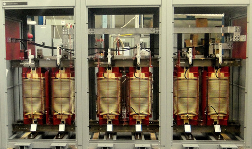
MGM has partnered with some of the largest utility companies in the country to provide transformers for High Rise buildings.Ê

Medium voltage distribution circuits are typically used in High Rise buildings because they offer higher efficiency and lower cost, and MGM’s High Rise transformers were developed specifically for these unique power distribution systems. In these systems, power circuits branch from the main high voltage bus to High Rise transformers which then step the voltage down to feed individual user’s panels. Using a medium voltage main bus is less expensive than a standard low voltage bus which requires larger cables and junction boxes.Ê

MGM’s units have other options which make them even more desirable in High Rise applications. They have far lower dB levels for indoor use and are equipped with special trip devised design to isolate the transformer in the event of a fire.Ê

  • IEEE C57.12.01 and IEEE C57.12.91
  • 1 or 3 Phase
  • 60 Hz Frequency
  • Up to 15 kV Primary Voltage
  • 60 kV, 95 kV, or 110 kV Primary BIL
  • Single, Delta or Wye Connections
  • 10 kV Secondary BIL
  • 80, 115, or 150¡C Temperature Rise
  • Aluminum or Copper
  • 4% or 7% Impedance
  • Standard voltage taps

STANDARD FEATURES
ADDITIONAL DETAILS

The transformer is a ventilated, open wound VPI dry-type. The coils are cooled by natural circulation of air through the windings.

The insulation system for the transformer windings is a UL¨ listed 220¡C (Class R). Winding layer insulation is DuPont Nomex¨.

The core is constructed of non-aging, high permeability grain oriented silicon steel. All core laminations shall be step-lap mitered cut, free of burrs and stacked without gaps. The core framing structure is of rigid construction to provide full clamping pressure upon the core and provide the support points for the coils. Coils are adequately braced for full short circuit capability.

The core and coil are supported by vibration isolation pads to effectively dampen vibration transferred to the transformer enclosure.

ENCLOSURE

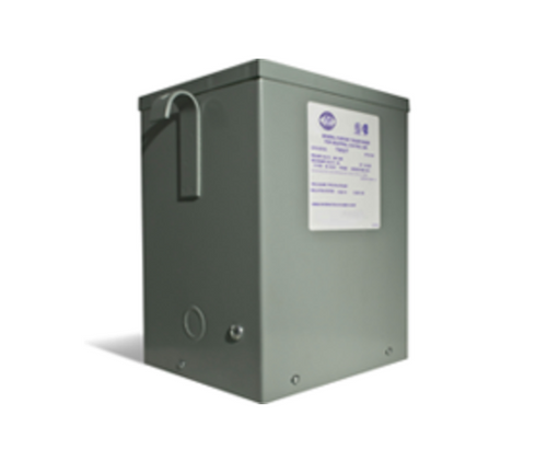
The enclosure includes provisions for rolling, skidding, lifting, and jacking for installation. All parts of the cabinet are made with at least a 12 gauge thickness. The bottom plate has openings to allow air in but theyÕre small enough to prevent rodents from entering. The front and rear panels have handles for easy removal. Side panels have cutout openings for cable entrance. TwoÊcover plates are provided for the openings. Lifting provisions are made of corrosion resistant material and so arranged to provide a suitably balanced lift for the completely assembled unit.

GROUNDING

A 2 inch stainless steel grounding is installed on the outside of the side panels above each of the cable knockouts openings. Each pad is provided with two holes horizontally spaced on 1-3/4Ó centers and tapped for _Ó-13 NC thread. Internal connection (by removable strap or cable of #4/0 copper capacity) is made from the core frame to either case grounding pad.

BUSHINGS

The high voltage is supplied with 200 amp bushings with removable stud on each ungrounded phase. Bushing are installed with a keeper plate / clamping ring furnished with grounding provisions. Bushing wells are installed in a top mounted removable fuse chamber for three-phase units and in the top fuse compartment section for single-phase units.

LOW VOLTAGE TERMINALS

The secondary is terminated with tinned spade type terminations sized to carry maximum nameplate loads. Terminals are located near the front of the enclosure at the base of the core and coil assembly in a horizontal configuration. Terminals have a minimum air clearance of 1.5 inches to the front panel.

The terminals are vertically offset from one another as much as possible but no less than 2 inches. The uppermost terminal is vertically positioned no less than 8 inches from the top edge of the lower panel.

ACCESSORIES

A thermally operated spring shorting switch is installed in the fuse compartment on the enclosure for each ungrounded phase in a manner which insures positive grounding of the load side of the fuse clip when the thermal switch is actuated. The thermal shorting switch assembly is shipped from the factory with the fusible link disengaged. Three phase shorting switches are designed to mechanically trigger all three switches simultaneously. A bare #2 copper ground wire shall be installed connecting the shorting switch to the ground bus or terminal.

Ê

Primary high voltage fast clearing current limiting type fuses are located horizontally in the upper fuse compartment for over-current protection. Three phase transformer fuse
compartments are removable. Fuses may be Òclip-styleÓ or incorporate load-breaking capability. Fuse ratings are to be specified by the customer to meet system and code requirements.

Reviews